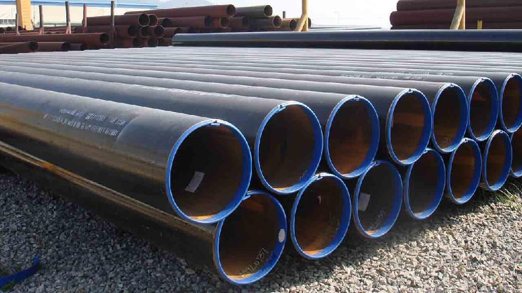
MS Pipes and Fittings Size Charts: The Ultimate Reference
Selecting the right pipe for any construction or engineering project is critical. Our detailed MS pipes and fittings size charts provide all the information you need in one place. They list all the outer diameters based on standard measurements, offer precise values for pipe weight per meter, detail the maximum pressure capacity for various pipe schedules, and present the chemical composition along with physical properties. This resource is designed for professionals who need clarity when converting from NB (nominal bore) size to OD (outer diameter) and vice versa.
Key Components of the Charts
Outer Diameters
- Accurate Measurements: Our charts feature the outer diameter of MS pipes in mm, ensuring that you have standardized data whether you work with imperial or metric systems.
- NB Size to OD Conversion: The conversion process from nominal bore (NB) sizes to the actual outer diameter (OD) is crucial. Our resource clearly outlines these conversions for simplified reference.
Pipe Weight Per Meter
- Exact Values: Knowing the weight per meter of a pipe is essential for structural design, cost estimation, and transportation. With our complete MS pipes size charts, you get an accurate pipe weight calculator integrated into the overall design.
- Tool Integration: Many users appreciate having a dedicated pipe weight calculator that quickly computes how much a particular pipe weighs, making planning and budgeting more precise.
Maximum Pressure Capacity
- Schedule 40 Seamless Pipes: Understanding the maximum pressure capacity of pipes is vital for ensuring safe operation when they are in service. Our charts list detailed values for maximum pressure of schedule 40 seamless pipes, helping you select the right grade and specification for your project.
- Industry Standards: The charts adhere to recognized standards so that you can trust the values provided for pressure capacity during design and implementation stages.
Chemical Composition & Physical Properties
- Material Specifications: Beyond dimensions, the charts also cover the chemical composition and physical properties of ASTM A106 MS Seamless pipes. These include tests for purity, strength, flexibility, and durability.
- Enhanced Decision Making: Including these details ensures that engineers and fabricators can choose a pipe not only based on size but also on material performance, making sure the pipes are fit for their intended use.
Why Use MS Pipes Size Charts?
- Standardization: Whether you’re working with imperial measurements or converting to metric, the ms pipes size charts are indispensable. The detailed breakdown from NB size to OD makes every conversion simple and straightforward.
- Enhanced Safety: With verified data on the maximum pressure of schedule 40 seamless pipes incorporated directly into the charts, you can ensure that the pipes you choose will reliably withstand the designated pressures.
- Cost-Efficiency: Using the integrated pipe weight calculator helps in precise budgeting, reducing waste and avoiding the pitfalls of underestimating transport or material costs.
- Comprehensive Guidance: The inclusion of chemical composition and physical properties offers deeper insights into pipe durability, performance, and compatibility with different engineering applications.
Read further to know about Flange Size Charts.
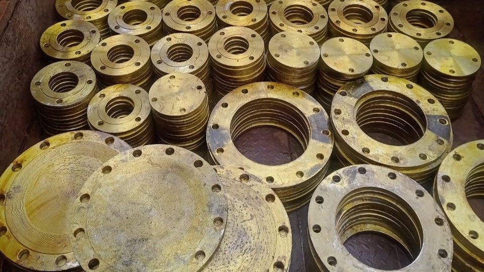
Steel Flanges Size Charts: A Comprehensive Guide
When it comes to selecting the right flanges for a piping system, understanding the exact dimensions and properties is key. Steel flanges size charts are indispensable tools that detail every parameter—from the overall outer diameters and thicknesses to the bolt circle diameters, number of bolt holes, and pressure ratings. These charts, especially for ANSI Class flanges, cover various standards such as ASA150, ASA300, and the British BS10 Table E and Table D formats.
What Are Steel Flanges?
Steel flanges are mechanical components used to connect pipes, valves, pumps, and other equipment to form a piping system. They ensure leak-free junctions and are critical for maintaining system integrity under high-pressure conditions. The standardized charts provide precise dimensions to match the pipe and operational demands, making them essential for design engineers, fabricators, and installation experts.
Key Attributes in Steel Flanges Size Charts
- Dimensional Data and Conversions: The charts specify various parameters including the flange’s outer diameter, thickness, and bolt circle diameter. For instance, comparing dimensions across recharts like ANSI Class ASA150 and ASA300 flanges helps engineers quickly verify compatibility with system requirements.
- Material and Pressure Specifications: Flange charts also list the maximum pressure ratings for each classification. Whether you are looking up the pressure capacity for an ASA150 flange or assessing the performance of ASA300 rated flanges, these charts provide the technical details necessary to guarantee reliability during operation.
- Standardization Across Multiple Formats: With increasing globalization, engineers often work with different standards. In addition to ANSI/ASA flanges, the charts now include details from BS10 Table E and Table D—standards commonly used in European and British applications. This unified approach ensures that you have all the information at hand regardless of the applicable regional standard.
- Comprehensive Data Tables: Below is a sample data table that represents the kind of information typically found on a steel flanges size chart.
Note: Actual values vary based on detailed standards, manufacturing tolerances, and specific applications.
Understanding the Different Standards
- ANSI / ASA Standards (ASA150 & ASA300): The American National Standards Institute (ANSI) and its derivative, ASA, define flange dimensions, tolerances, and pressure classes. ASA150 and ASA300 flanges are differentiated by their pressure ratings and corresponding design verifications. Designers rely on these charts to determine the correct component for high-pressure applications.
ANSI-B16.5 / ASA 150 Flange Dimensions
ANSI-B16.5 / ASA 300 Flange Dimensions
Check out the official website of American National Standards Institute: ansi.org. - BS10 Table E and Table D: In the United Kingdom and other regions following British standards, BS10 flanges are commonly referenced. Table E and Table D provide detailed dimensions and tolerances that cater to different applications. These tables complement the ANSI charts, ensuring that designers working on international projects have a comprehensive reference that meets both American and British standards.
BS10 Table D Flange Dimensions
BS10 Table E Flange Dimensions
Why Steel Flanges Size Charts Matter
- Accuracy and Safety: With detailed dimensions and specifications, these charts help ensure that the selected flange meets the necessary safety and design criteria, avoiding potential failures during operation.
- Design Efficiency: Having all the standardized data on-hand allows engineers to quickly cross-reference dimensions, convert nominal sizes, and verify compatibility. This leads to faster design cycles and robust installation practices.
- Global Applicability: Whether you’re dealing with an ANSI Class flange or working within the framework of BS10 standards, the comprehensive steel flanges size charts ensure that you have unified and precise data for all your project needs.
Final Thoughts
A well-prepared steel flanges size chart is much more than a simple list of numbers—it is a critical tool that supports efficient design and high safety standards. By having access to charts that cover ANSI Class ASA150 and ASA300, as well as BS10 Table E and Table D, professionals can confidently choose the right components for their projects.